.......................................
Transcranial Direct Current Stimulation
.......................................
================================
INTRODUCTION
================================
This Instructable got cited by a reputable source (pdf link)! Citation #10 in the paper "New tools for neuroenhancement - what about neuroethics?"(html link) Croat Med J. 2016 Aug; 57(4): 392-394. doi: 10.3325/cmj.2016.57.392 ------- Some concern about the ethics of this sort of activity, warnings about changes in personality and hormones as a result of use of tDCS. So I added some warnings.
Site for different tDCS
placements and effects.
View this project in the context of my life and intent on my own site here if you wish.
Edit: If you want hardware to do tACS and tRNS in addition to tDCS, I've built some of that too.
I was surprised and pleased to learn that human enhancement technologies not only exist, but are within the reach of the basic electronic hobbyist. This instructable is (of course) for educational purposes only and you may be violating local laws by constructing and/or using the device described here. The author of this instructable is not liable for the burns, permanent neurological damage, or other personal injury up to and including insanity and/or seizures and/or dismemberment and/or immolation and/or death that may result from building and using the device described here.
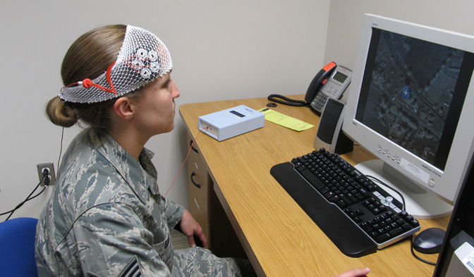
Transcranial Direct Current Stimulation (tDCS) is a method of external neural modulation that uses a small current run through the brain in order to alter cortical excitability. The details of the mechanism of action and exact enhancements possible are beyond the scope of this article, but you can examine commercially available products, and look at safety data and ethical reviews before deciding if this is something you would like to pursue. Some google scholar searches will turn up interesting things too.
The first photo on this page is from this article.
================================
CIRCUIT PRINCIPLE OF OPERATION
================================
If you don't wish to consider the theoretical basis for the
operation of this circuit, skip this step.
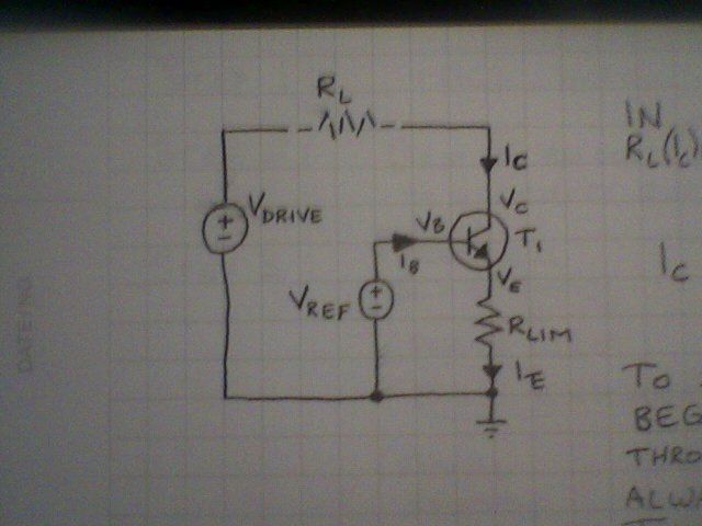
The circuit
shown is a regulated current sink. You may find it a useful building
block in your future projects. It regulates the current through R[L],
preventing it from exceeding a set value. This circuit doesn't have
active drive capacity, though, and so V[DRIVE] must be large enough
to drive the desired current through R[L].
The current
through R[L] is equal to I[C]. I[C] is roughly equal to (
V[REF] - (V[BE] of T1) ) / R[LIM] .
To see where this
equation originates, begin by noting that the sum of the voltages
around the loop formed by V[REF], the base-emitter junction of T1,
and R[LIM] must be zero (by Kirchhoff's voltage law):
V[REF] -
V[BE] - V[RLIM] = 0
so
V[RLIM] = V[REF] - V[BE] .
The
current through R[LIM] (also known as I[E]) is defined by Ohm's law,
and we can substitute using the previous equation:
I[E] =
V[RLIM] / R[LIM] = (V[REF] - V[BE] ) / R[LIM] .
Ignoring
the base current,
I[C] = I[E] ,
so the current through the
load resistor is approximately defined by
I[LOAD] = I[C] =
(V[REF] - V[BE] ) / R[LIM] .
If you wish to include the
effects of the base current of the transistor, you must also factor
in the current gain of the transistor, h[FE].
Viewing the
transistor as a node, by Kirchhoff's current law,
0 = I[C] +
I[B] - I[E]
so
I[B] = I[E] - I[C] .
We know that
h[FE] is the factor we can multiply by I[B] to find our I[C].
Thus,
I[B] * h[FE] = I[C] .
Substituting for I[B]
from a previous equation,
(I[E] - I[C]) * h[FE] = I[C]
.
Solving for I[C],
I[C] = I[E] - (I[E] /(1 + h[FE] )
) ,
and since I[E] = (V[REF] - V[BE] ) / R[LIM] ,
the exact
equation then becomes:
I[C] = ((V[REF] - V[BE] ) / R[LIM]
) - (((V[REF] - V[BE] ) / R[LIM] ) / (1 + h[FE] ) ) .
================================
PRACTICAL ASSEMBLY
================================
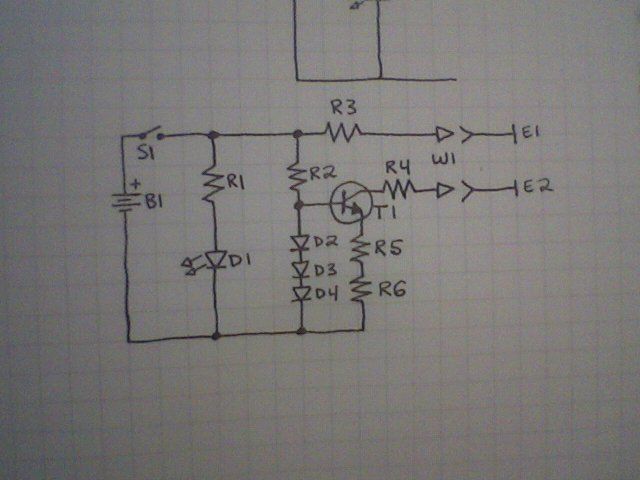
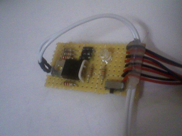
This is the schematic of a working 2mA current supply that may be
used for tDCS. It is based on the transistor regulator described in
the previous step. Parts were added to allow on/off functionality, on
state indication, and redundant safety measures.
---PARTS
LIST---
B1: 4 9V battery clips, series configuration (add 9V
batteries to provide power)
S1: SPST switch
D1:
indicator LED
D2-D4: 1n400x (I used 1n4003)
T1:
TIP31C (or TIP29C)
R1,R2: 12 kohm 250mW
R3,R4: 2.2
kohm 250mW
R5: 560 ohm 250mW
R6:100 ohm 250mW
Wires
and gel electrodes are easiest to find sold for TENS devices, but
will allow tDCS, though only in areas that are hairless. There are
other options, though, and sponge
electrodes are less likely to cause electrode burns.
Original suggestion at the initial time of writing, the cheapest,
but can only be used over hairless skin and may be more likely to
cause skin irritation and minor damage:
W1: electrode leads
(such as these TENS leads)
A search for "TENS electrode leads" will find the appropriate type
http://www.amazon.com/s/ref=nb_sb_noss_1?url=searc...
E1,E2: gel electrode pads (also sold for TENS units)
Search for "TENS gel electrodes", I recommend 2" x 2" square gel electrodes
http://www.amazon.com/s/ref=nb_sb_noss_1?url=searc...
New suggestion 1: sponge electrodes that are compatible with 2mm pin connectors instead of gel electrodes. That's an ebay link, though, posted 2016-10-24, and it may not remain live / I can't find any other sellers with 2mm compatible sponge electrodes at the moment.
New suggestion 2: Banana plugs instead of TENS electrodes leads and Amrex sponge electrodes. Those sponge electrodes are $20 each, though, instead of $10 for a pair like new suggestion 1.
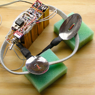
New suggestion 3: Someone who followed this design (Instructables username ElChevere) used spoons and kitchen sponges for electrodes. Of this I wholeheartedly approve, since it's probably the cheapest / most efficient way to get sponge electrodes with commonly available parts :)
Image below:
================================
TESTING AND QUALITY VERIFICATION
================================
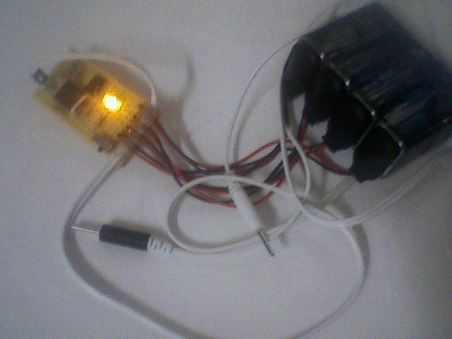
Once your device is constructed, you should test it before
adhering it to your head and torso and activating it. Check the
short-circuit output current with an ammeter. The value should be 2
mA +/- 10%.
Have fun. Try to get better.
Look
into piracetam
but remember that it seems to work best when taken with supplemental
choline.
Good
luck.