tACS design log
[obligatory blurry picture of alpha prototype device]
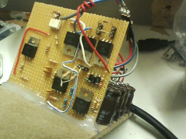
[non-blurry picture of alpha prototype]
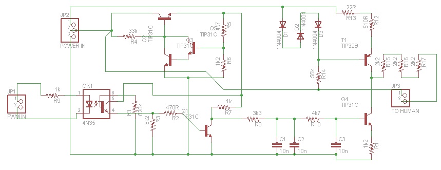
[device schematic (does not include power supply)]
We are developing a computer-controlled tDCS/tACS/tRNS device. The output will be internally limited to prevent it from exceeding a two milliamp output current (positive or negative) regardless of what commands are issued to it by the computer via USB. Using software alone it will be possible to tell the device to output DC (up to two milliamps, either polarity) or any AC signal (up to 1kHz frequency, peak value limited to +/- 2mA) from a sine wave (for tACS) to random noise (for tRNS).
Currently, the tACS hardware is midway through development. We've built a physical prototype, but its output fails to meet our specifications due to nonlinearity and minor instability. We suspect these to be caused by the output transistor operating near cutoff when output current approaches maximum. This will be corrected in the next hardware iteration by moving the bias point of the output transistor so that it is in a more linear region of operation throughout the circuit's +/-2mA output range. Furthermore, the use of PWM (pulse width modulation) to control the output current leads to ripple (45 microamps peak-peak in our prototype), and engenders awkward design tradeoffs between output slew rate and ripple current. We will eliminate these undesirable characteristics in the next hardware iteration by using a dedicated DAC to control the output instead of a PWM channel.
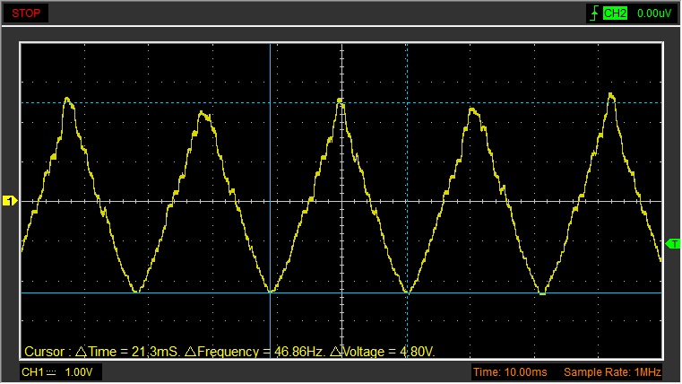
Current prototype output, 47Hz triangle wave, 2.4mA peak output current (measured as voltage across 1k resistor in series with dummy load (humans with gel electrode connections are about 5.35k for those wondering))
The alpha hardware design (done in Cadsoft EAGLE), in a zip file containing a circuit for simulating the prototype output module in LTSPICE, and the schematic and board -- board untested (built the prototype on perfboard), schematic values R6 and R12 required tuning to achieve the results shown in the oscilloscope image above.
Eagle-eyed readers will note that the LTSPICE and EAGLE versions of the schematic are slightly different. We're too busy working on the next design revision to bother making sure the documentation of our buggy alpha hardware is perfect.